ESP8266 has a single ADC pin available. It may be used to read voltage at ADC pin or to read module supply voltage (VCC).
When referring to the ADC pin these terms are used interchangeably: ADC (Analog-to-digital Converter), TOUT, Pin6, A0 or Analog0.
Check your Wi-Fi module. The ESP8266 A0 pin supports a maximum voltage of 1.0V. Many newer Wi-Fi modules have an on-board voltage divider to support a higher A0 input voltage range (typically in the range between 0 and 3.3 volts). You may need to use an external voltage divider to ensure your input voltage is in the right range.
By default Tasmota uses ADC pin to read voltage. The signal comes from an analog peripheral, or sometimes from the device itself (see Shelly 2.5).
After wiring a peripheral to A0 pin you have to configure it in Configure Module:
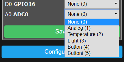
| # | Option | WebUI display | MQTT mesage |
|---|---|---|---|
| 0 | None | none | none |
| 1 | Analog | Analog0 %value% | {"A0":%value%} |
| 2 | Temperature | Temperature %value% °C (°F) | {"Temperature":%value%},"TempUnit":"C"} |
| 3 | Light | Illuminance %value% lux | {"Illuminance":%value%} |
| 4 | Button | none | none |
| 5 | Buttoni | none | none |
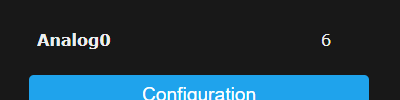
The reading will show in web UI's sensor section as "%option% %value%" depending on the selected option. Tasmota calculates the values for temperature and light, analog values can be 1 to 1024.
Example: ADC as Analog (1)
A message will be published in tele/%topic%/SENSOR JSON response as "ANALOG": depending on the selected option.
Example: ADC a Light(3) 18:55:09 MQT: tele/tasmota/SENSOR = {"Time":"2019-10-31T18:55:09","ANALOG":{"Illuminance":8}}
Careful when setting ADC as Button, if there is constant voltage on the pin it might register as a long press and reset the device to firmware defaults
Rule triggers
Use these triggers in rules:
on ANALOG#A0div10 do ... - when the ADC input changes by more than 1% it provides a value between 0 and 100
on Tele-ANALOG#A0 do ... - triggers on tele messages with Analog object
MQT: tele/tasmota/SENSOR = {"Time":"2019-01-14T19:36:51","ANALOG":{"A0":1024}}
Rule example: using a potentiometer on analog pin.
ADC_VCC
Instead of an input, ADC pin can be used to measure supply voltage of the ESP module (this reading in not 100% accurate). To enable ADC_VCC feature you need to compile your own build:
If you enable ADC_VCC you cannot use the pin as analog input anymore.
user_config_override.h flag:
// -- Internal Analog input -----------------------
#define USE_ADC_VCC                              // Display Vcc in Power status
Supply voltage is published in tele/%topic%/STATE under "Vcc": in mV:
11:14:59 MQT: tele/tasmota/STATE = {"Time":"2019-10-31T11:14:59","Uptime":"0T18:36:12","UptimeSec":66972,"Vcc":3.423,"Heap":28,"SleepMode":"Dynamic","Sleep":50,"LoadAvg":19,"MqttCount":6,"POWER":"OFF","Wifi":{"AP":1,"SSId":"Tasmota","BSSId":"00:00:00:00:00:00","Channel":13,"RSSI":100,"LinkCount":1,"Downtime":"0T00:00:06"}}