Buttons and switches are primarily used to toggle (turn ON or OFF) device relays. A typical device usually has at least one button (exception being bulbs and some lights) to control the relay(s). Additional buttons and switches can be wired to a free GPIO and configured in Module or Template settings.
Other than relays, Tasmota does not publish the state of components (switches, buttons, sensors, etc.) in real-time. Only messages corresponding to relays are transmitted in real-time. The state of components is transmitted automatically each TelePeriod via the
SENSORSmessage.
Button vs. Switch
A button (also called a push-button) is a momentary or non-latching switch which causes a temporary change in the state of an electrical circuit only while the switch is pressed. An automatic mechanism (i.e. a spring) returns the switch to its default position immediately afterwards, restoring the initial circuit condition.
A switch (more precisely a latching or toggle switch), when activated by the user, remains in that state until activated again.
Learn more about buttons and switches in this video.
Both have a similar function, but Tasmota distinguishes between a "Button" and a "Switch" in other ways.
Button
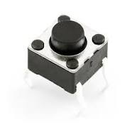
For Tasmota, a Button is typically a momentary push-button (or a capacitive touch button in some light switches). By default a button toggles the corresponding relay. Every time the button gets pressed the relay changes its Power state (ON or OFF). Besides toggling the Power state, a button is also used to activate multi press button functions, to do long press (HOLD) actions, or send messages to different MQTT topics. See Button-usage for a detailed multi-press function list, ButtonTopic options, and changing default Button functionality.
A push-to-make button should use a Button<x> component while a push-to-break button should use Button<x>i (i.e., inverted).
Switch
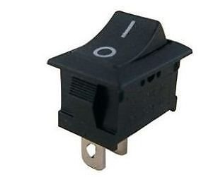
In Tasmota a Switch is any switch or push-button additionally connected to a free GPIO. Some possibilities include:
- mechanical toggle switch - also called a rocker switch
- capacitive touch switch
- reed switch
- PIR - even though it's technically a sensor it is configured as a switch in Tasmota
- mechanical push-button
By default a switch toggles the corresponding relay. Every time the switch gets flipped, the relay changes its state (ON or OFF). Instead of the default toggling of the relay, switches can be configured to send messages to different MQTT topics or send commands to other Tasmota devices. To ignore the default behaviour define a rule which triggers on Switch<x>#State or use Switchtopic.
Example rule to make Switch1 publish its value to cmnd/custom-topic/SWITCH:
Rule1 on switch1#state do publish cmnd/custom-topic/SWITCH %value% endon
Rule1 1
Now, to make everything a little confusing: A push-button can be configured as a
Switchand a toggle switch can be configured as aButton. Configuring a toggle switch as aButtonis not recommended!
SwitchMode
For visual learners: Tasmota Switchmode Explained - video by Dr Zzs
To change the behavior of a physical input peripheral configured as a Tasmota Switch<x> component, whether a toggle switch or a momentary switch (i.e., a push-button), use the SwitchMode command. If there is more than one Switch<x> component, use SwitchMode<x> where <x> is the number of your switch from the Tasmota GPIO configuration.
SwitchMode, as the name implies, applies ONLY to GPIO configured in Tasmota as a Switch<x> component (9-16 & 82-89). SwitchMode has NO impact on the behavior of GPIO configured as Button<x> components (17-20, 90-93, & 112-129). SwitchMode sets the desired behavior of a Switch<x> component based on whether it's a switch or a push-button (i.e., a momentary switch) that is physically connected to the GPIO.
SwitchMode 0
Default mode
Set switch to toggle mode.
Tasmota sends TOGGLE command each time the state of the circuit changes (closing or opening).
SwitchMode 1
Set switch to follow mode (0 = OFF, 1 = ON)
At the time when the circuit is closed, Tasmota will send ON and opening the circuit sends OFF.
You want to use
SwitchMode 1when connecting a toggle switch (e.g. a classic light switch) to your device. This way the "software switch" will mirror the state of the "hardware switch". If the real switch is in the "ON" position, the state in Tasmota isONas well.
SwitchMode 2
Set switch to inverted follow mode (0 = ON, 1 = OFF)
At the time when the circuit is closed, Tasmota will send OFF and opening the circuit sends ON.
When connecting a momentary switch (i.e., a push-button) you will want to use
SwitchMode 3..7.
SwitchMode 3
Set push-button mode (0 = TOGGLE, 1 = ON (default))
Tasmota will send a TOGGLE command when the button is released (opening the circuit). When pressing the button (closing the circuit) nothing will happen. Default state is ON and when pressed it's OFF. (This trigger is known as falling-edge)
SwitchMode 4
Set inverted push-button mode (0 = OFF (default), 1 = TOGGLE)
Tasmota will send a TOGGLE command when the button is pressed (closing the circuit). When the button is released (opening the circuit) nothing will happen. Default state is OFF and when pressed it's ON. (This trigger is known as rising-edge)
SwitchMode 5
Set push-button with long press mode (0 = TOGGLE, 1 = ON (default), long press = HOLD)
Tasmota will send a TOGGLE command when the button is released (opening the circuit). When pressing the button (closing the circuit) nothing will happen. Default state is ON and when pressed it's OFF. When held for the time set in SetOption32 (default = 4s), Tasmota sends HOLD (use Switch#state=3 in rules).
SwitchMode 6
Set inverted push-button with long press mode (0 = OFF (default), 1 = TOGGLE, long press = HOLD)
Tasmota will send a TOGGLE command when the button pressed (closing the circuit). When the button is released (opening the circuit) nothing will happen. Default state is OFF and when pressed it's ON. When held for the time set in SetOption32 (default = 4s), Tasmota sends HOLD (use Switch#state=3 in rules).
Long press or hold can be used in conjunction with rules to create additional features or to control another Tasmota device.
SwitchMode 7
Set toggle push-button mode
Tasmota will send a TOGGLE command when pressed and another TOGGLE command when released.
For example, when the button is pressed, toggle the relay to ring the doorbell; when the button is released, ring the doorbell again.
SwitchTopic
SwitchTopic and ButtonTopic are almost identical in use. You can use this guide interchangeably for both or read ButtonTopic.
Note about SwitchTopic (or ButtonTopic) and MQTT
When using SwitchTopic 1 or 2 (or ButtonTopic 1 or 2) and your MQTT broker becomes unavailable, Tasmota falls back to default SwitchTopic 0 (or ButtonTopic 0), which is not optimal.
To avoid this, we recommend using rules. They simply always work!
If you still need to use SwitchTopic or ButtonTopic, read on!
SwitchTopic 0
Default mode
By default a switch controls the corresponding relay and doesn't send any MQTT messages itself.
No MQTT message will be published on account of the new switch state. The message you see in console is the new state of the relay that is controlled and not the switch state.
SwitchTopic 1
Sets MQTT switch topic to device %topic%
When changing the state of the switch an MQTT message is sent to the device topic with the payload according to SwitchMode set.
Example: Device topic tasmota, SwitchMode 3 yields the following message.
MQT: cmnd/tasmota/POWER = TOGGLE
Notice the cmnd instead of the stat at the beginning.
This is the same as sending an MQTT commands to this device, the device relay will be set to the defined state.
SwitchTopic <value>
Set switch topic to a custom topic (32 characters max)
This will send an MQTT message to a custom defined topic similarly to option 1.
For example, we set the topic to tasmota02 with SwitchTopic tasmota02.
Example: Device topic tasmota, SwitchMode 1, custom topic tasmota02 yields the following message.
MQT: cmnd/tasmota02/POWER = ON
If you have a device with the topic tasmota02 this action will turn on its relay while not affecting anything on the tasmota device.
In summary
SwitchTopic 0 controls the relay directly.
SwitchTopic 1 sends an MQTT message to the device topic. This sets the state of the devices relay accordingly.
SwitchTopic <value> sends an MQTT message command to the custom topic. This does not change the state of the devices relay.
For a practical application of everything mentioned in this article read about this excellent LEGO nightstand switch project.