Starting with Tasmota version 6.5, devices can be configured by users using a Template.
These are intended to be an easy way for users to create and share configurations for devices that are unsupported in Tasmota but have common characteristics with existing modules. We encourage everyone who creates a template for a new unknown device to add it to the database with an image of the device, links to the manufacturer or where it can be found and, of course, the template for it.
To provide easy processing by Tasmota, a user template is written as a JSON string and could look like this:
{"NAME":"UserModule1","GPIO":[17,148,29,149,7,255,255,255,138,255,139,255,255],"FLAG":0,"BASE":18}
More about template properties at the bottom of the article.
Template configuration
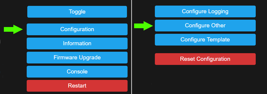
Go to Configuration - Configure Template ...
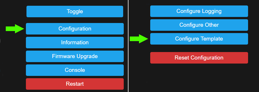
... and you'll end up looking at this screen.
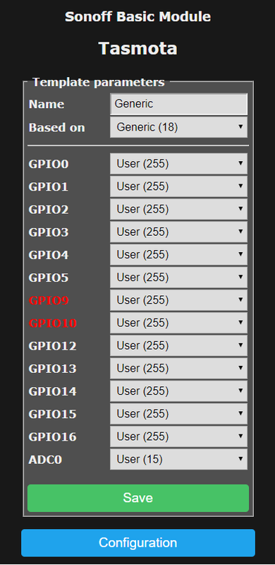
Time to create your template.
Creating your template
-
Change
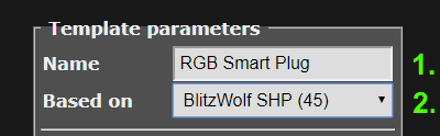 the template name (also defines the name for the module).
 -
Select a module to BASE your template on. If you're not sure,
Module 18is the best choice. In this example the device is based on Blitzwolf SHP (45) module. -
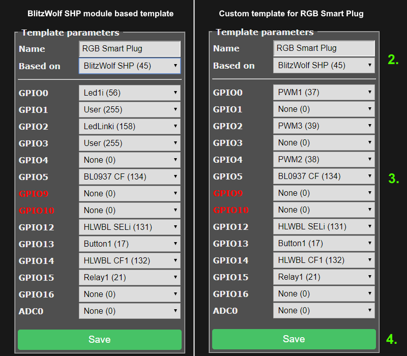
Configure the components assigned to the GPIOs to match your device. If you do not know what pins your device uses, read about the new device configuration procedure to determine the correct pin assignments.
-
Any unused GPIO that has cannot have a peripheral connected should be set to
None (0). In our example the device has no exposed GPIO's so the unused ones are set to0compared to the original BlitzWolf module. -
GPIOs that can have peripherals connected to (exposed GPIOs) should be set to
User (255). This allows future configuration through the Configure Module dialog without the need to create a new template.A
Sonoff THis a good example. It has a jack connected to GPIO4 that allows a user to plug in a sensor. Assigning GPIO4 as255allows a Template to have correct for this device even if nothing is plugged in. But, when a user decides to connect a sensor using the jack, GPIO4 can be set to the type of sensor through the Configure Module page.
-
-
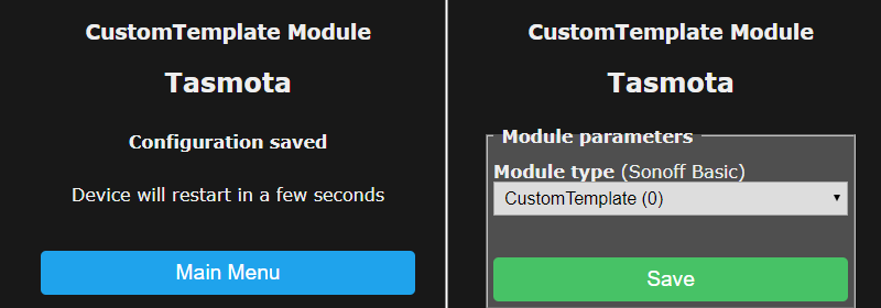
Click on Save and you'll see this message

- Finally, the device will reboot with the new template name
Exporting your Template
Now that you've set up your previously unsupported device in Tasmota it is time to share the knowledge:
- Check that
Module 0is selected in the Configuration - Configure Module menu. - Open up Console and issue command
Templatewhich will output a string with the configuration of your currently active template. Our example gives the following:
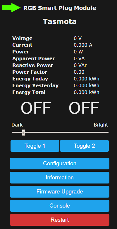
MQT: stat/tasmota/RESULT = {"NAME":"RGB Smart Plug","GPIO":[37,0,39,0,38,134,0,0,131,17,132,21,0],"FLAG":0,"BASE":45}
Copy the string {"NAME":"RGB Smart Plug","GPIO":[37,0,39,0,38,134,0,0,131,17,132,21,0],"FLAG":0,"BASE":45} and share it on the Tasmota Device Templates Repository.
Importing Templates
Go to Configuration - Configure Other
When there:
- Paste the template string into the Template field
- Make sure you check Activate
- Click on Save.
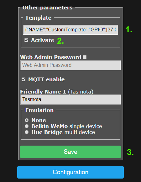
The device will reboot with a name reflecting your template name and Module 0 selected which has your new template stored.
Merge Template and module settings
You can set up your device in module Configuration - Configure Module and use command Template 255 to merge the settings of the Module with current template into a new Template named "Merged".
Template configuration with commands
A user provided template can be stored in Tasmota using the Template command. It has the following parameters.
| Parameter | Description |
|---|---|
|
Show current Template |
0 |
Create template from active module |
1..71 |
Create template from a supported module |
{ ... } |
Store template written in a JSON string |
Template {"NAME":"UserModule1","GPIO":[17,148,29,149,7,255,255,255,138,255,139,255,255],"FLAG":0,"BASE":18} stores a complete template based on the Generic module
Template {"NAME":"AnotherModuleName"} updates the name of a stored template
Template {"FLAG":0} changes FLAG value
Template {"BASE":18} updates the base of a stored template to Generic
After setting a template in command line it is necessary to issue Module 0 command if the device doesn't reboot on its own.
Explanation of template properties
Let's look again at our example template:
{"NAME":"UserModule1","GPIO":[17,148,29,149,7,255,255,255,138,255,139,255,255],"FLAG":0,"BASE":18}
The four properties with UPPERCASE property names have the following functionality:
| Property name | Property value description |
|---|---|
| NAME | Up to 14 characters for the Module name |
| GPIO | Up to 13 decimal numbers from 0 to 255 representing GPIO0 to GPIO5, GPIO09, GPIO10 and GPIO12 to GPIO16 |
| FLAG | 8 bit mask flag register |
| BASE | Module number of a hard-coded device to be used when device specific functionality is needed |
GPIO
GPIO order
GPIO# |00| 01|02| 03|04| 05| 09| 10| 12| 13| 14| 15| 16|
CODE  [17,148,29,149,52,255,255,255,138,255,139,255,255]
GPIO functionality
The GPIO functionality numbers are the same as shown by command GPIOs. In addition code 255 is added to select a GPIO as user configurable via the GUI Configure Module menu.
example
In our example the GPIO 00 data element is
17which corresponds to theButton1component, according to the following table. If you change that template element to9it would then be assigned as aSwitch1component instead.
Components
See Components for a complete list
Google Sheet with the components by number or alphabetically.
FLAG
Used to configure the ADC type. In most templates this should be set to 0.
| FLAG | Feature description |
|---|---|
| 0 | No features |
| 1 | Analog value |
| 2 | Temperature |
| 3 | Light |
| 4 | Button |
| 5 | Buttoni |
| 15 | User configured (same as GPIO 255) |
BASE
BASE is the starting module setup for the custom template. Some modules include special programming. If your device is similar to an existing built-in module it is best to use that as a starting point. When you're not sure which BASE module is suitable for your device use the Generic (18) module. A list of hard-coded devices can be found in Modules.
example
In the RGB Smart Plug template we used the
BlitzWolf SHP (45)module as BASE since the power monitoring circuitry is identical but GPIO00 and GPIO02 were changed and an unused GPIO04 was added to enable the RGB LED function. Using that specific module we took advantage of that module's calibrated power monitoring special programming which theGeneric (18)module does not use.