Table of Contents
So far I analyzed it is equipped with these chips:
- ESP-12F
- STM32F-030C8T (Cortex M0)
- Winbond 25Q32 (EEPROM)
- 74HC245
- XL1509 3.3E1 (Step down regulator)
- RX/TX of STM is connected to ESP.
- 74HC245 buffers the outputs
ESP is connected to the STM RX/TX pins. No other connections seen. We can assume there is some firmware in the STM that does the low level connection to the LEDs.
Question is how does the ESP communicate with the STM and what exactly does the STM at all. But we can mod the hardware so the ESP can talk to the LEDs.
I made some pictures with phone and microscope.
PCB

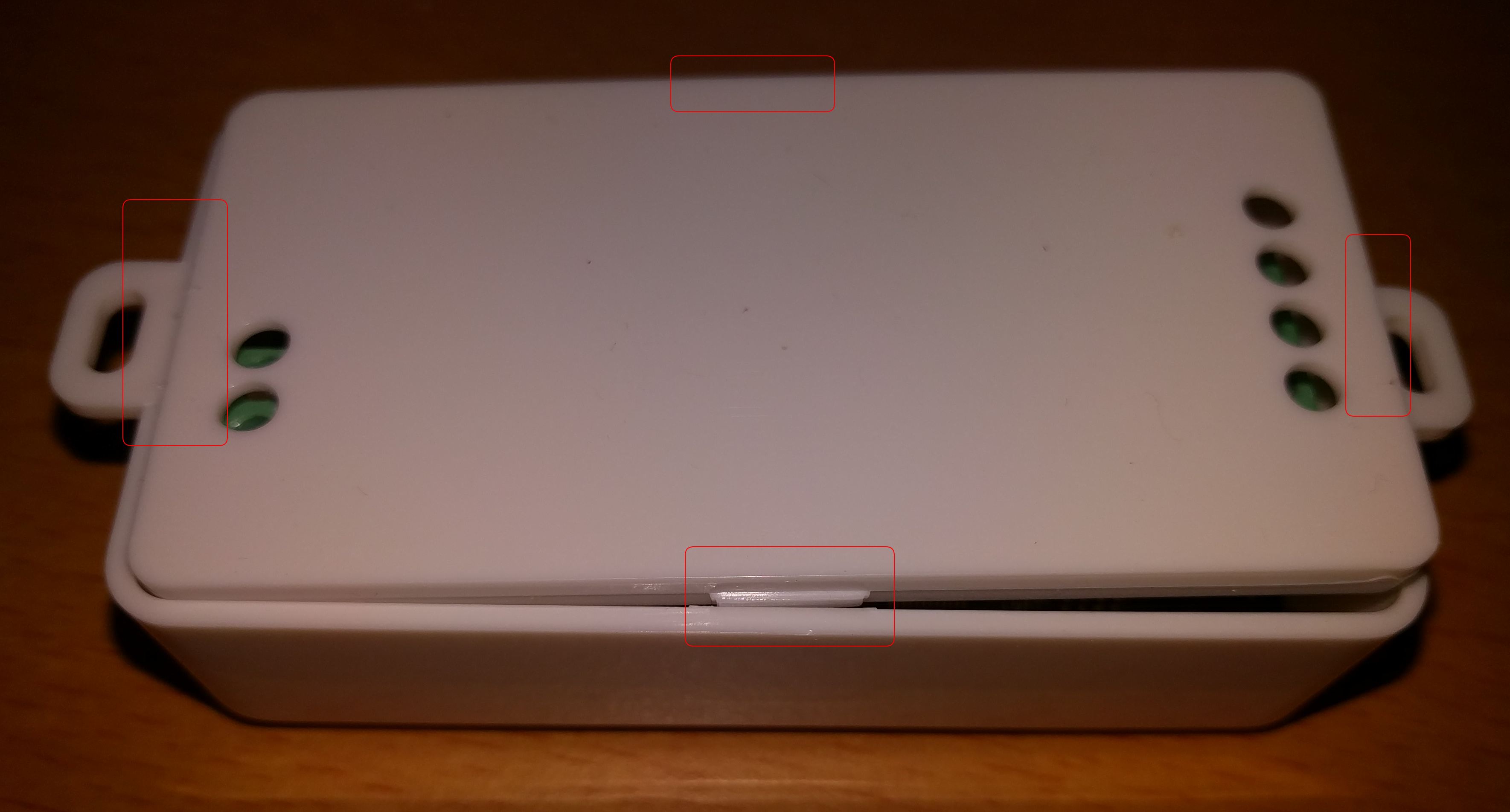
Open the housing, see the red marks for the holders)
RX/TX connection ESP to STM

STM32F0

EEPROM

Pins lead to the STM32F0 (Firmware flash? Debug?)

ESP-12 and its pins


Buffer chip 74HC245

Traces on bottom side from STM to HC245 (actually R3 and R4)

For the hardware mod to make it working without the STM32F0, there are several ways:
1. Cut traces and add wires
We need to break one of the traces on the bottom of the PCB. Then connect GPIO4 of ESP-12 with R4. Also RX/TX connection between STM32F0 and ESP-12 need to be broken up.
2. Hold STM32F0 in reset
This is the simpler method, no cuts on the PCB required, just two additional wires.
- NRST of STM32F0 to GND
- IO4 of ESP-12 to R4
See here for details.
Flashing prohibited
Major problem right now is that IO0 is directly connected to VCC, so we cannot bring ESP-12 into flash mode. Working on a solution.
Wiki has moved to link on the left.