This model sells for about $20 on Amazon.
Info on the Tuya
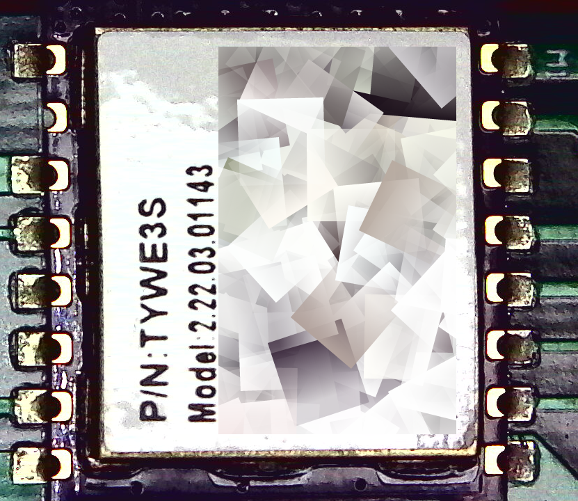
The chip inside is a Tuya TYWE3S. It replicates the capabilities of an ESP8266 plus some other functionality.
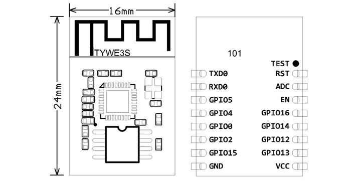
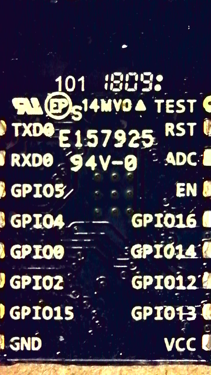
NOTE: THE RIGHT SIDE IS THE BACK OF THE BOARD. RST IS ON THE TOP LEFT OF THE LEFT PICTURE, AS WELL AS THE TOP LEFT OF THE PICTURE BELOW.
Here’s a picture of the chip inside the switch:
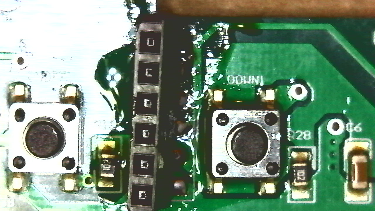
Pin 1 is labeled M1 in the silkscreen of the switch board. Here’s the back, I desoldered it with my Quick 861DW:
On the other side of the board is an apparent test/programming header labeled CN1:
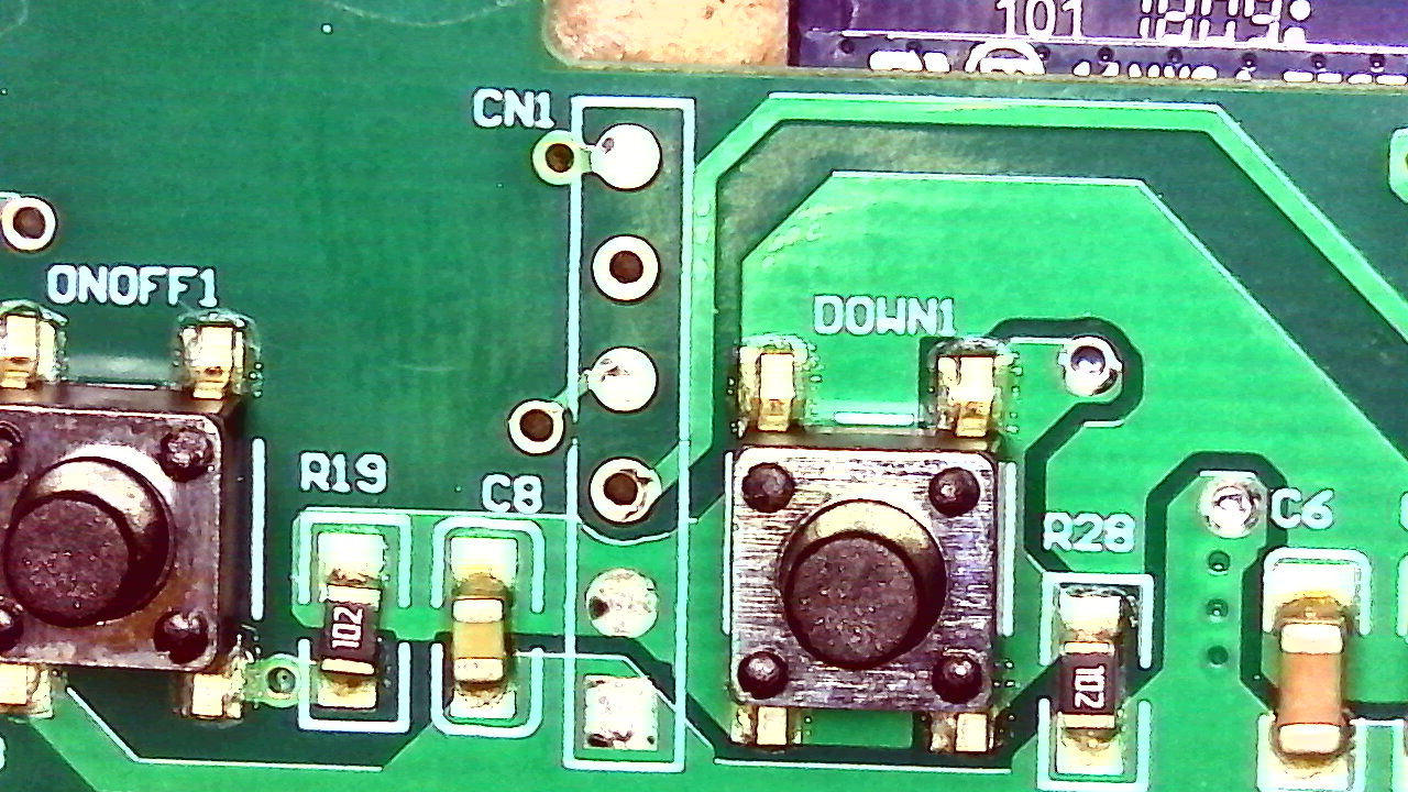
From top to bottom on CN1 above, they are:
| Pin | Signal |
|---|---|
| CN1-1 | TXD |
| CN1-2 | RXD |
| CN1-3 | GPIO2 |
| CN1-4 | GPIO0 |
| CN1-5 | GROUND |
| CN1-6 | VCC |
See Tasmota Hardware Prep for more details
I removed all the crappy lead-free solder and put on a little strip of female pin header:
Now I can easily hook it all up to the breadboard!
I erased the firmware using the instructions using a Raspberry Pi 3 Model B. I couldn’t get the board into programming mode by grounding the reset pin through the breadboard, so I just held the UP1 button while connecting 3V3 and it worked fine.
There’s another 4-wire connector that goes to the AC board. The wires are as follows:
| Wire | Description |
|---|---|
| Black | 3.3v consistent, probably to power the other side |
| Purple | Variable voltage tied to dimmer. Low to high it’s: 360mV, 680mV, 1.32V, 1.94V, 2.57V, 3.20V |
| White | GPIO16 |
| Red | Ground |
The other side features an STC15W404AS chip. This is the closest information sheet I’ve found so far. It’s likely there’s an ADC receiver on the other side receiving our variable voltage on the purple wire above and converting that to the AC dimmer signal.
When probing with the oscilloscope I noticed a 3.3v 1Khz square wave on GPIO13. It turns out this is the PWM that controls the output of the purple wire. This is done using the positive duty cycle of the wave. Here’s a state table:
| Setting | Duty |
|---|---|
| 1 (Min Setting) | 20% Duty |
| 2 | 40% Duty |
| 3 | 60% Duty |
| 4 | 80% Duty |
| 5 (Max Setting) | 100% Duty, constant 3.3v |
We should be able to generate this same wave with whatever duty cycle we want in Tasmota to get much better dimming resolution than the default firmware provides.
The buttons are tied as follows:
| Button | Description |
|---|---|
| UP1 | GPIO0 to GROUND when pushed |
| DOWN1 | TXD to GROUND when pushed |
| ON/OFF | 3.3v to GPIO15 when pushed |
| RESET | Wired through an LED and resistor to GPIO16, also goes to white wire (RESET for the STC?), ties to GROUND |
The LEDs are wired as follows:
| LED | Description |
|---|---|
| LED1 | Passthrough to RESET, GPIO16, see above. |
| LED2 | GPIO14 |
| LED3 | GPIO12 |
| LED4 | GPIO5 |
| LED5 | RXD |
Added a new entry to the sonoff_template.h list and assigned all the pins. You can of course just do a generic load and set it up with the Web UI. Here's what I ended up with in the header:
{ "MJ-SD01",         // Martin Jerry Smart Dimmer Switch (ESP8266EX)
     GPIO_SWT3,        // GPIO00 UP1 Button, bright up
     GPIO_SWT2,        // GPIO01 Serial TXD and DOWN1 Button, bright down
     0,        // GPIO02
     GPIO_REL5,        // GPIO03 Serial RXD
     GPIO_REL1_INV,        // GPIO04 Multi-LED RED
     GPIO_REL4_INV,    // GPIO05 LED1
     0, 0, 0, 0, 0, 0, // GPIO06-GPIO11
     GPIO_REL3_INV,        // GPIO12 LED3
     GPIO_PWM1,        // GPIO13 PWM for dimmer
     GPIO_REL2_INV,        // GPIO14 LED2
     GPIO_SWT1,        // GPIO15 ON/OFF Button, ties to 3.3v when pushed
     GPIO_SWT4,        // GPIO16 RESET button, also goes to AC side and probably resets the STC chip, tied to LED1
     0                 // ADC0 Analog input
  }
- FADE ON: Makes the PWM movements smooth
- DIMMER +/-: Moves dimmer up and down
- SPEED 3: Slows down fade a little
- SETOPTION15 1: Sets DIMMER mode rather than PWM
Now that you can have rules set on dimmer actions, changing the LEDs with dimmer settings should be easy. I tried to do this before that existed, and it wasn't possible.