Table of Contents
Discussed here
Configuration
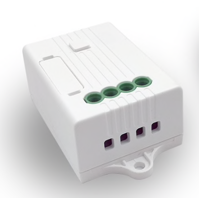
Configure as a Tuya Dimmer (54) (support as a BASE module was introduced in 6.2.1.16).
-
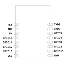
GPIO13 - Tuya Rx (108)
-
GPIO15 - Tuya Tx (107)
-
Template: {"NAME":"Kinetic Switch","GPIO":[255,255,255,255,255,255,0,0,255,108,255,107,255],"FLAG":0,"BASE":54}
Flashing
This device uses a Tuya TYWE3S Wi-Fi PCB module. An easy soldering method is to take several Dupont style jumper wires, cut one end off, and apply a bit of solder to each stripped end. This will keep the wire flexible and prevent any circuit board pads from ripping off. Apply a bit of solder to each pad necessary to flash (double check your pin-outs). Once the wire and pad have solder simply put the two together and apply a bit of heat and they will join together.
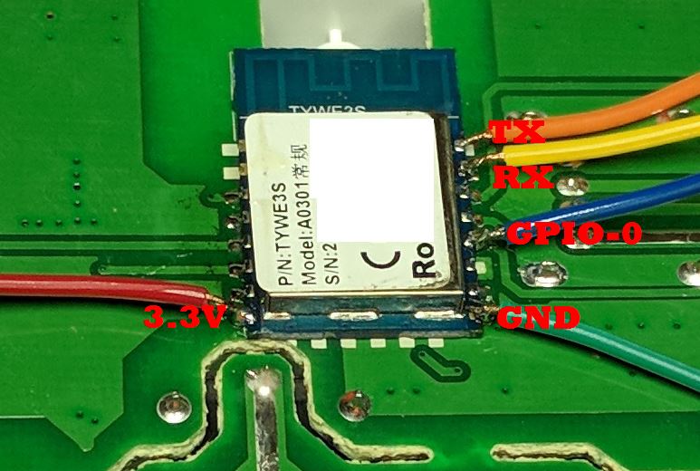
Attach the GPIO0 wire to ground during initial boot to flash. A 3-pin header bridged together works great with GPIO0, GND and the GND from the USB flasher attached (TX pin to RX pin and RX pin to TX pin on USB flash adapter). Verify that you are using 3.3volts to flash, NOT 5V!
Two options:
-
Remove the ESP PCB by desoldering. This makes it easier to get to the pins of the TYWE3S board.

-
No PCB desoldering. You will have to connect the RESET pin of the MCU chip to GND. This requires a soldering iron with a thin tip.

Wiki has moved to link on the left.