A generic touch dimmer flashed with Tasmota.
On AliExpress you can buy a wifi dimmer for mains voltage (110 or 220V) It's a brandles dimmer, but can be found here: AliExpress page
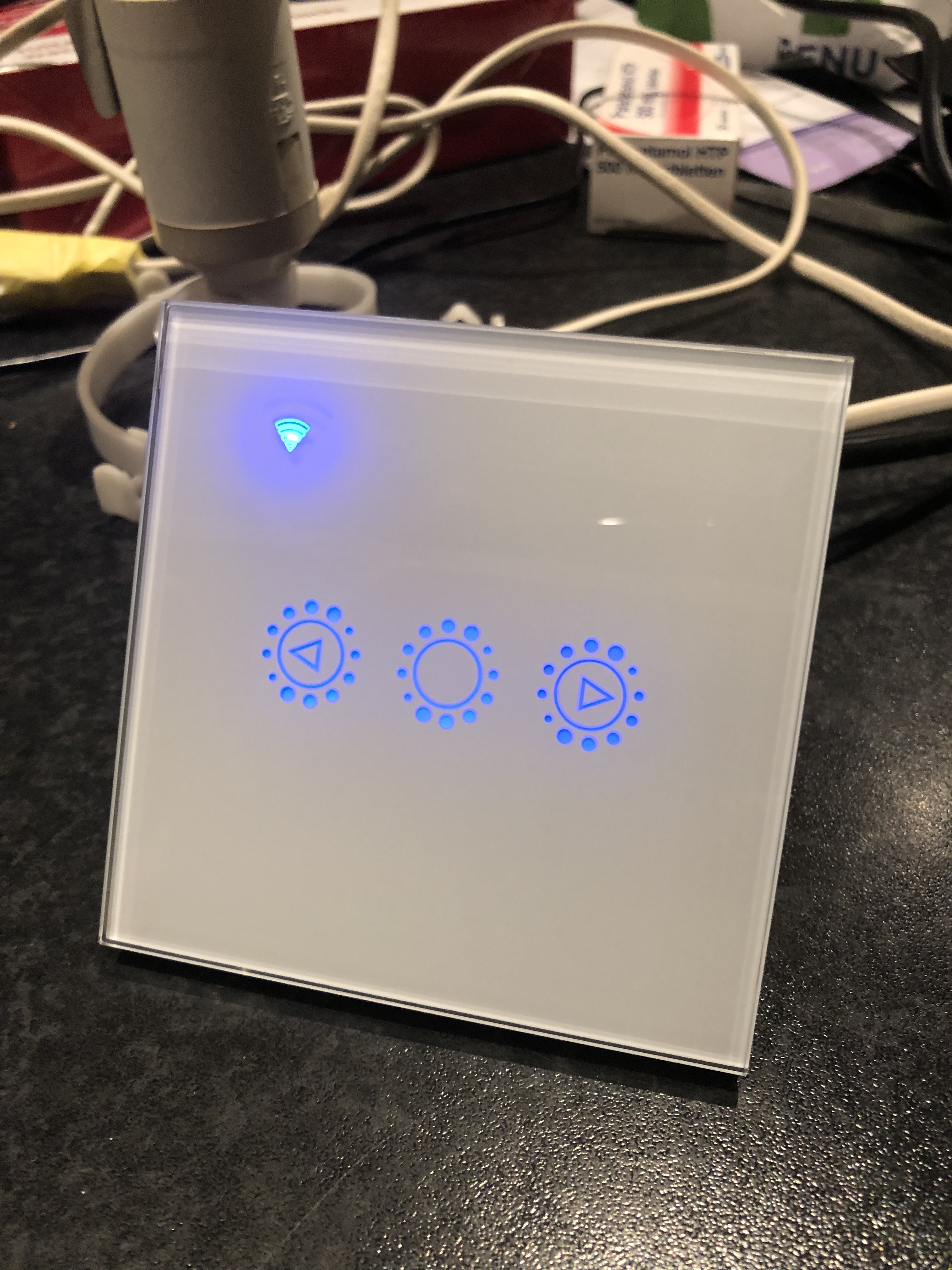
It comes in a couple of forms, but sinds I live in Holland, I chose the EU style, single gang, 220V, White edition. It has a glass front plate with 3 proximity/touch switches (On/Off, dimm up & dimm down) and a wifi indicator LED.
The inside houses 2 PCB's; a power board and a control board:
The control board:
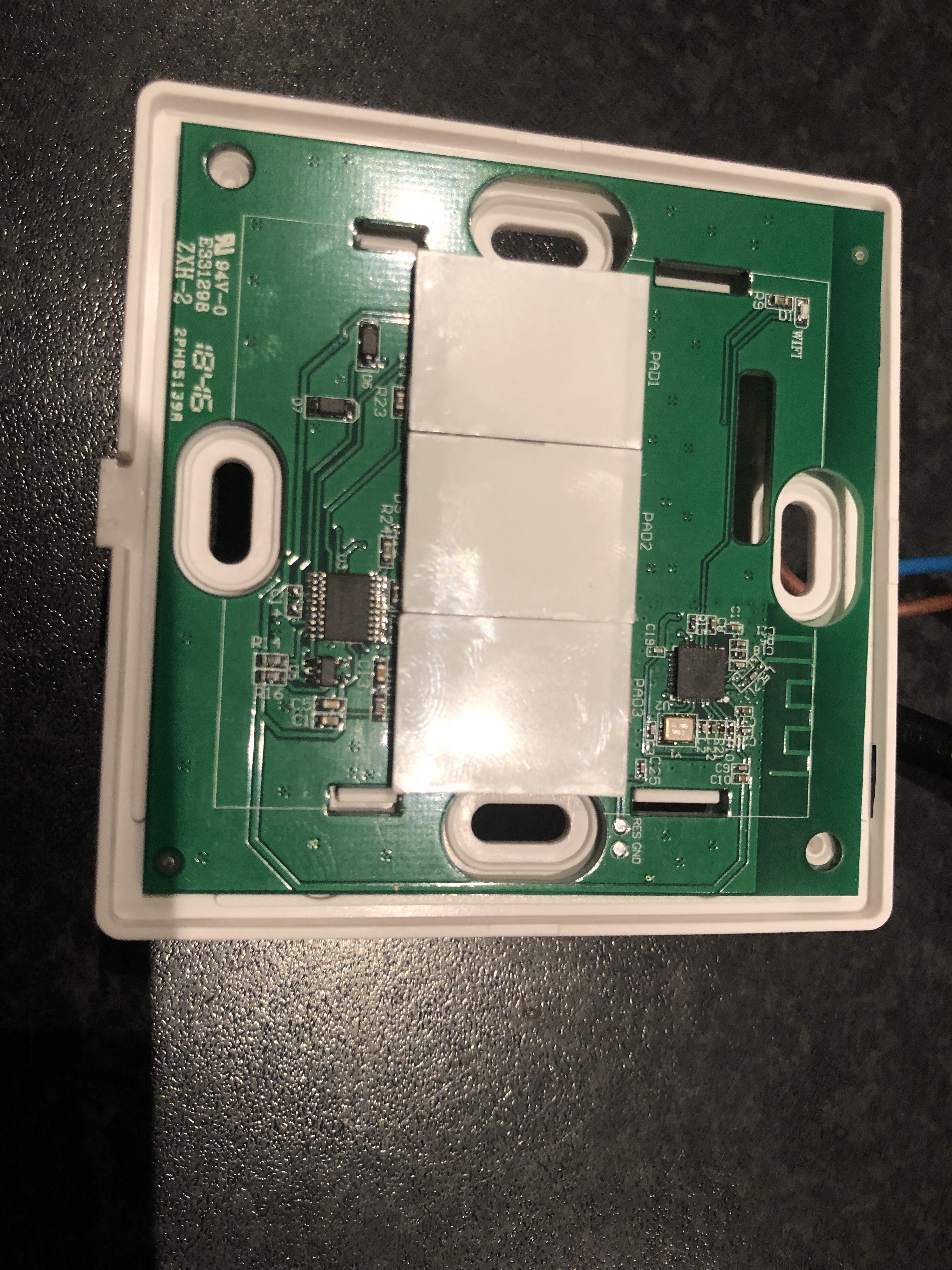
There are two main chips on board: An ESP8266 and a Nuvoton n76e003at20 The Nuvoton will do the switch side of it all, the ESP communication.
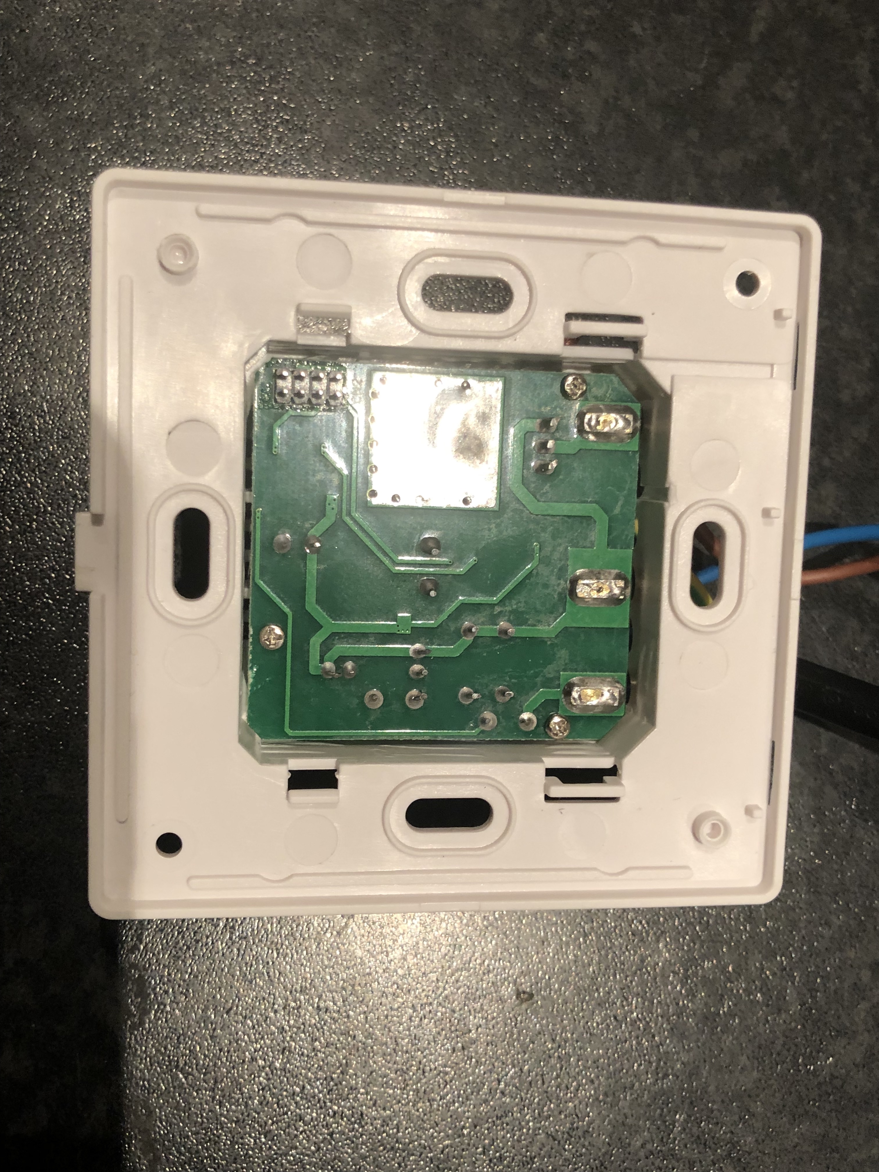
The mains board:
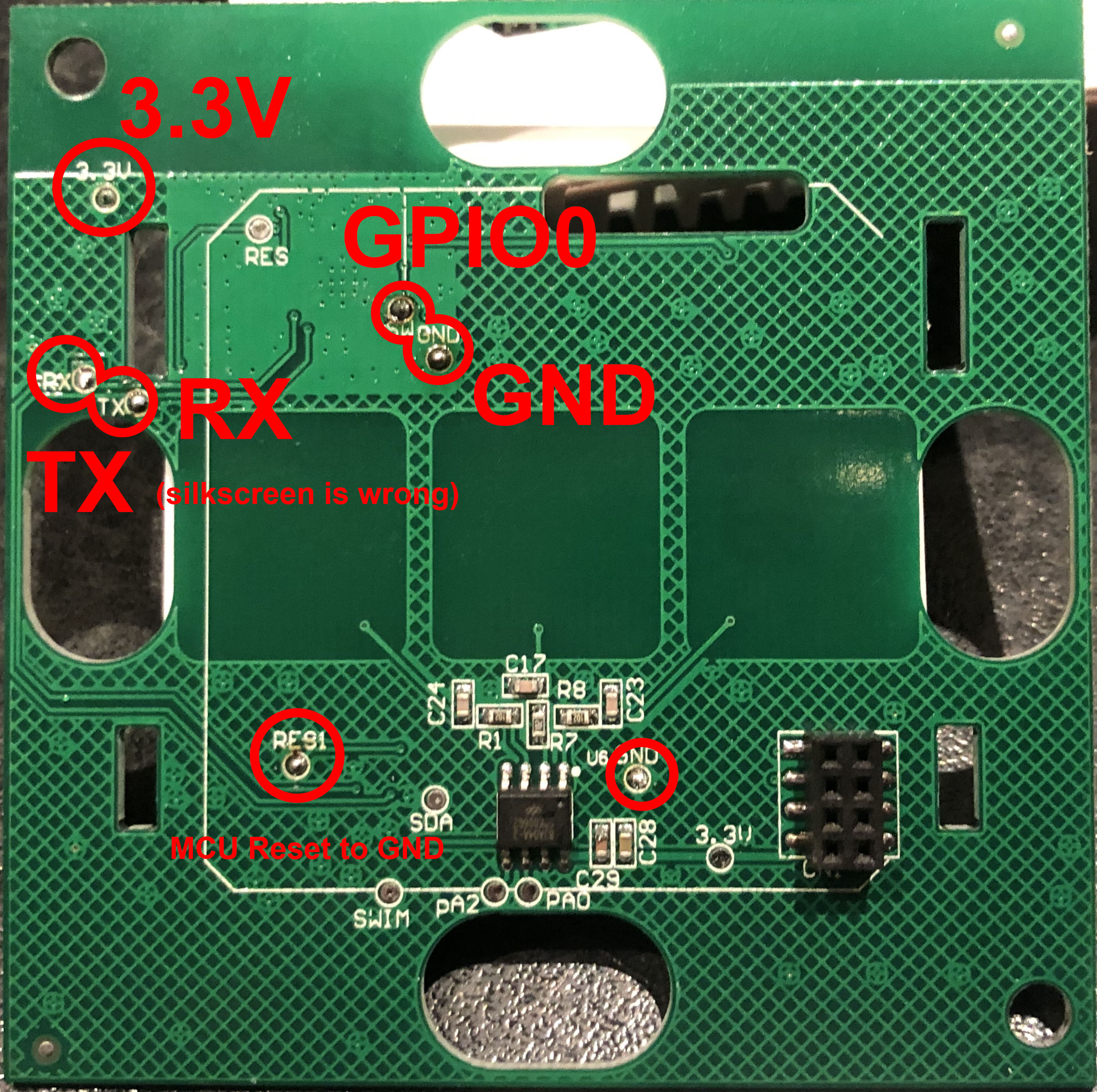
For flashing, we only need the control board. Solder small wires to the pads as marked on the picture:
-
3.3V
-
GND
-
RX
-
TX
-
Sw (gpio0)
-
Solder 'Res1' to GND
Note that the silkscreen on this board has TX and RX wrong.
Now use a USB to serial adapter to connect the wires.
Use a 3.3V board, NOT 5V, this will destroy the ESP chip on the board!
Connect:
GND to GND
3.3V to 3.3V
RX to RX (due to the fact the silkscreen is wrong, otherwise, RX connects to TX and vice versa)
TX to TX
SW to GND -- only during power up, to put the ESP in programming mode.
From here the upload is the same as for all other Tasmota devices. See the Tasmota page for detailed info.
Note: sonoff basic and classic variants do not support the serial bridge. To get this working you should use the standard tasmota.bin - NOT basic or classic.
After the upload was successful, unplug the device from the serial adapter. You can now desolder all the connections you have made earlier. Also remove the wire between RES1 and GND. Then plug the board back in its housing. Be careful with the connector on the underside of the board. Line up the pins with te header and lightly press it in its place.
Connecting to mains installation:
WARNING! THIS PROJECT INVOLVES WORKING WITH HIGH VOLTAGE AND YOU COULD KILL YOURSELF AND/OR SET YOUR HOUSE ON FIRE.
Connect your light to the dimmer according the manual. Keep in mind, the dimmer itself needs a Neutral wire as well. If you replace an existing switch or dimmer, it can be that you need to run an extra neutral wire.
First connection
When you first power up the dimmer switch, it comes up in AccessPoint mode. Follow the instructions here
Set correct module type
Once you have all connected, you should go to the configuration page of the Tasmota Dimmer. Go to your browser and fill in the IP address. Then go to 'Configuration' and then to 'Configure Module'.
From the drop down menu select module 58: PS-16-DZ. Then hit Save.
The module will restart and you are done!
 You can now toggle the light and use the slider to dim the lights from the tasmota webpage.
Or better, use your favorite domotica software to control it via MQTT.
You can now toggle the light and use the slider to dim the lights from the tasmota webpage.
Or better, use your favorite domotica software to control it via MQTT.