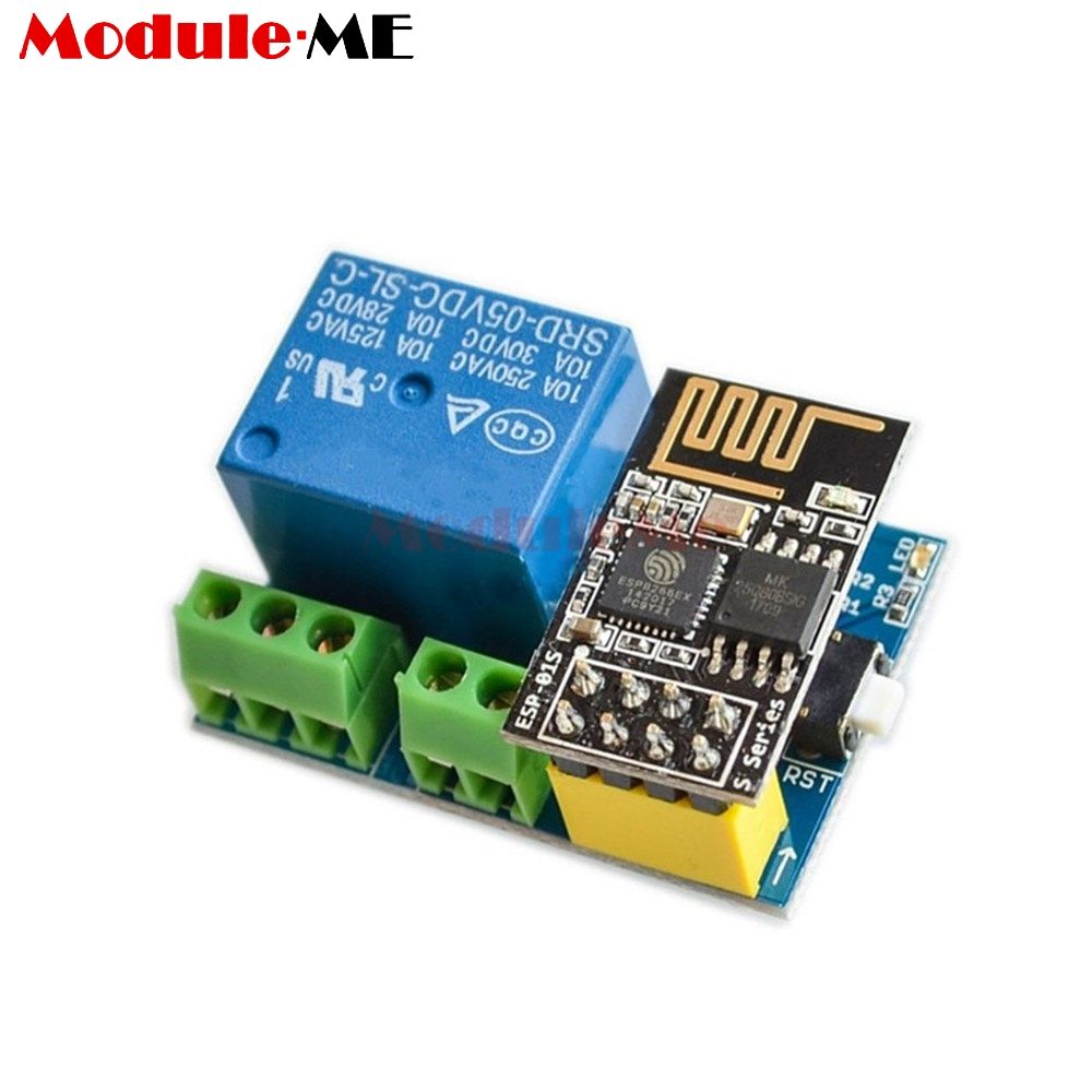
LC Technology WiFi Relay - Single Relay
The LC Technology relay devices use GPIO1 and GPIO3 for the serial communications used to control the relays. You do not need to specify these in the template. SerialSend uses these standard serial communications GPIO by default.
In order to use LC Technology WiFi Relay for 1 relay version:
- Set module to Generic (18) (in module configuration and click save)
- Set D3 GPIO0 as Relay1 (21) (in module configuration and click save)
- Disable SerialLog (type
seriallog 0in the Tasmota console) - Add the following rules typing in the console:
Rule1 on System#Boot do Backlog Baudrate 9600; SerialSend5 0 endon on Power1#State=1 do SerialSend5 A00101A2 endon on Power1#State=0 do SerialSend5 A00100A1 endon - Enable the rule (type
rule1 1in the Tasmota console) - Note: If that doesn't work for you, you may find that using
Power1#Bootas the event to trigger the baud rate setting (instead ofSystem#Boot) works, as it did for me. So the alternate rule is:on Power1#Boot do Backlog Baudrate 9600; SerialSend5 0 endon on Power1#State=1 do SerialSend5 A00101A2 endon on Power1#State=0 do SerialSend5 A00100A1 endon
LC Technology WiFi Relay - Dual Relay (note, older versions of this board used a baud rate of 9600, so if 115200 doesn't work, try 9600)
To configure an LC Technology ESP8266 Relay X2, use the following settings...
- Set module to Generic (in module configuration and click save)
- Set GPIO0 and GPIO2 as Relay1 and Relay 2 (in module configuration and click save)
- Disable SerialLog (type
seriallog 0in the Tasmota console) - Add the following rules typing in the Tasmota console:
Rule1 on System#Boot do Backlog Baudrate 9600; SerialSend5 0 endon on Power1#State=1 do SerialSend5 A00101A2 endon on Power1#State=0 do SerialSend5 A00100A1 endon on Power2#State=1 do SerialSend5 A00201A3 endon on Power2#State=0 do SerialSend5 A00200A2 endon - Enable the rule (type
rule1 1in the Tasmota console)
LC Technology WiFi Relay - Quad Relay (note, older versions of this board used a baud rate of 9600, so if 115200 doesn't work, try 9600)
In configuration open Configure Other paste this template and select activate
{"NAME":"LC Technology 4CH Relay","GPIO":[52,255,17,255,255,255,255,255,21,22,23,24,255],"FLAG":0,"BASE":18}
Enter this command in console (configure the 1st rule)
Rule1
 on System#Boot do Backlog Baudrate 9600; SerialSend5 0 endon
 on Power1#State=1 do SerialSend5 A00101A2 endon
 on Power1#State=0 do SerialSend5 A00100A1 endon
 on Power2#State=1 do SerialSend5 A00201A3 endon
 on Power2#State=0 do SerialSend5 A00200A2 endon
 on Power3#State=1 do SerialSend5 A00301A4 endon
 on Power3#State=0 do SerialSend5 A00300A3 endon
 on Power4#State=1 do SerialSend5 A00401A5 endon
 on Power4#State=0 do SerialSend5 A00400A4 endon
Enable the rule (type rule1 1 in the Tasmota console)
Beware of counterfeit modules
If your board just continuously flashes its led when powered on and no esp-01 is entered, the onboard STC15F104W needs to be programmed! For more details (link)
Additionally, once programmed, you may also have to remove r4. Some issues exist where r3 and r4 are swapped, but just removing r4 works.