⚠️ ⚠️ ⚠️
DO NOT PERFORM THIS MODIFICATION WITHOUT REMOVING POWER FROM THE PZEM FIRST!
⚠️ ⚠️ ⚠️
Note: the PZEM-016 TTL output is at 5V signal levels. There are varying schools of thought on whether the ESP82xx has 5V tolerant GPIO. You may want to use a level shifter for the serial communications signals to bring them to the recommended 3.3V.
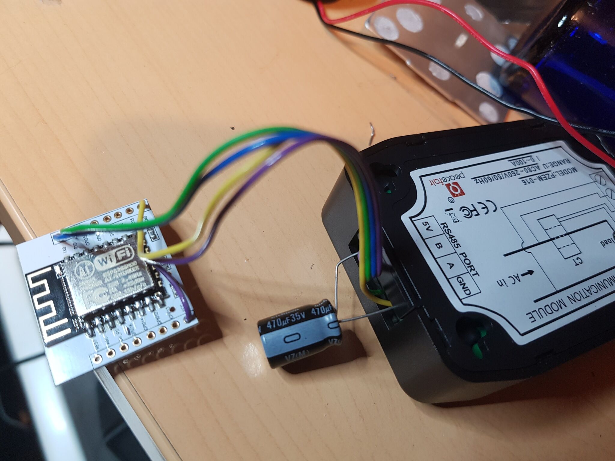
PZEM-016 modules can be converted from RS485 to TTL serial level devices by simply removing the internal MAX485 chip and adding two internal jumper wires. This will bring the serial port connections out via the four-pin terminal block. Pin A is now TTL serial out (Tx) and pin B TTL serial in (Rx). The modification retains the optical isolation used by the PZEM for safety to ensure no high voltages on the outputs.


You can use a voltage level shifter to power the ESP82xx from the PZEM-016 module's 5V power. This may also require a 470uf 35V capacitor across the 5V line to work reliably.
Tasmota Configuration
It is recommended to use GPIO1/GPIO3 or GPIO13/GPIO15 for the most reliable serial communications. You can use any GPIO but anything else will use serial emulation (software). Software serial is not supported with the 2.3 Arduino Core.
| GPIO | Component | PZEM |
|---|---|---|
| 1 | PZEM0XX Tx (62) | Pin B |
| 3 | PZEM016 Rx (98) | Pin A |
Wiki has moved to link on the left.