June 2019 - Devices delivered with Sonoff v3.3.0 stock firmware.
Serial flashing works for this device. You may wish to check whether the Sonoff DIY flashing method works if this device is upgraded to v3.3.1.
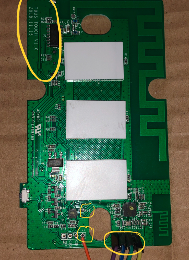
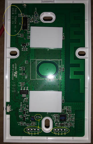
Board label: T0US TOUCH v1.0 2008.11.15
- TX T0 US, 1-3CH boards are physically the same.
- Only need the "top board" to flash (not the bottom relay part) -- don't power with mains (you can't if you only use top anyway)
- R19 is tied to GPIO 0 to enter flash mode, just like on T1 but in a different spot for t0 (or US?).
- Find the C2 (j1) pins and look directly up about half inch for r19
- Ensure that you select 3.3v and not 5v! to flash the board.
- ESP8285 - 1M - DOUT - erase flash - 115200 baud
Like the T1, this does not have enough room to solder a header on.
Use a piece of thick cardboard to lay your top board on. Firmly press some jumpers through the serial holes into the cardboard.
If you push these through at an angle will be good enough to make contact to connect to your serial adaptor, trial and error but is not hard. See photo below.
Regular flashing steps apply: connect Ground, Vcc TX, RX to your serial adaptor. Pay attention to TX/RX!
For flash mode, use another jumper through the ground hole on the C2 pins (left of the serial and label J1). Same as above, push the jumper through cardboard to secure it.
While powered off hold the other end of jumper to R19 and then power up (plug in your USB serial adaptor).
Hold it for 3-5 seconds after it powers up before removing it.
You should not see the network status led flash anymore, then you know you're in flash mode. If its flashing power off and try again.
Using the TX T1 1-3 device template will work. A new T0 template is forthcoming.
Start-to-Finish Flashing Guide
Flashing
- Connect the device's serial interface pins to the Serial-to-USB adapter. Be sure that your adapter is set to supply 3.3v. Place a jumper wire from GND to the side of R19 nearest the screw hole cutout - this is connected to GPIO0.
- Download
tasmota.binfrom http://thehackbox.org/tasmota - Have
NodeMCU PyFlasherrunning with the correct settings. Be sure to selectDOUTandErase flash - yes. Select the right COM port for your serial-to-USB adapter and selecttasmota.binfrom the folder where you downloaded the file. - Plug the serial adapter into the USB port and click the
Flashbutton onNodeMCU PyFlasher. - When you get the flash complete, remove the GND jumper wire from GPIO0.
- Cycle power on your device by disconnecting the serial adapter from the USB port for a couple of seconds and plugging it back in.
IP Configuration
- Using a mobile device, scan for Wi-Fi networks and connect to the
sonoff-xxxxaccess point. When it connects to the network, you may get a warning that there is no Internet connection and be prompted to connect to a different network. Do not allow the mobile device to select a different network. - Open the browser on your mobile device and navigate to http://192.168.4.1.
- In the Tasmota web UI, scan wifi networks and select the network for your home. Then enter the network's password (click the checkbox to see the password you enter to ensure that it is correct and that your mobile device has not inadvertently capitalized the first letter if it is supposed to be lower case nor autocorrected what you entered). When you save the settings, the device will restart and connect to your home network. The
sonoff-xxxxnetwork will not longer be present. Therefore your mobile device will automatically be disconnected and should connect back to its data network. - Check in your router or use an IP scanner to ensure that the device is connected to your home network. Make not of the IP address assigned to your device.
MQTT Configuration
- Go to new IP address (http://
IP) in a browser. - Click Configuration->Configure MQTT->
- MQTT Host: Enter the address (192.168.xx.yy or Hostname) of your MQTT broker. If you use the Home Assistant embedded broker, this will be your HA server.
- User: Enter the username for your MQTT broker
- Password: Enter the password for your MQTT broker
- Topic: Enter the unique MQTT topic for your device
- Save your settings. The device will restart
Device Configuration
- Click Configuration->Configure Module->Module Type->Sonoff T1 3CH (30) (the appropriate module for your device model) and save. The device will restart.
- Test the operation of the switches from the web UI. You should hear the relays click.
- Click Console
- If you use Home Assistant, enter
SetOption19 1to enable device auto-discovery. - Check the log for any errors.
Reassemble the switch and connect it to mains power. Check in your router or use an IP scanner to ensure that the device is connected to your home network. Also use the Tasmota web UI to ensure the switch is operating as expected.
Home Assistant Configuration
- Open TasmoAdmin via Hassio and Autoscan
- In Name1->Name3 enter switch position names again (note: understand orientation of switch)
- Go to ‘Devices List’ and check/test buttons click
- Click Cog configuration and enter names again and save
- Click Cog configuration, go to MQTT and change Group Topic to swtheatre and save
- Go to Devices List again and the circle arrows to restart the device
- Go to Integrations->MQTT and find the new switch and rename/locate items accordingly