PN532 HSU Driver for Tasmota
The PN532 is a highly integrated transceiver module for contactless communication at 13.56 MHz based on the 80C51 microcontroller core.
The datasheet for the PN532 chip is available here: https://www.nxp.com/docs/en/nxp/data-sheets/PN532_C1.pdf
Please note that although the datasheet mentions that the PN532 can be used on SPI, I2C and HSUART that only the HSU interface is implemented in the Tasmota driver.
PN532 Breakout boards
Since the PN532 chip itself is surface mount and requires some external components to operate the best is probably to obtain a breakout board similar to the one below from your favourite online supplier.
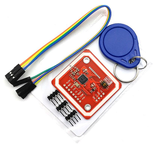
Please make sure the breakout board you order has the HSU pins (SCL=TX and SDA=RX) broken out as it will be very difficult to add them manually - Usually they have them but for good measure just make sure.
PN532 Configuration in Tasmota
The driver for the PN532 is not included in any of the default release binaries so you will need to compile your own binary for the purpose of using the PN532.
To enable it prior to compilation you need to add the following one or more lines in your user_config_override.h file, depending on your use-case (don't use Core 2.3.0, the core has issues with software serial).
Please note that the DATA field functionality has proven to work on some cards/tags but not all cards/tags - Please see Issue https://github.com/arendst/Tasmota/issues/4941 for more information about this.
#define USE_PN532_HSU
#define USE_PN532_DATA_FUNCTION
#define USE_PN532_CAUSE_EVENTS
The latter is only necessary if you need to perform actions on the local device using rules. If you only plan to handle the resulting scanned information on your home automation software then you do not need to uncomment #define USE_PN532_CAUSE_EVENTS as it has no use if you are not going to take an action on the device itself.
Please note that USE_PN532_DATA_FUNCTIONS are experimental - See Issue https://github.com/arendst/Tasmota/issues/4941 for more information as we are still researching the limitations of this usage because it seems not all cards are supported by this driver and/or the PN532 module.
Once you have compiled and uploaded your new firmware you will need to configure the usual (such as your wifi configuration and MQTT server configuration etc) and when complete proceed to enable GPIO pins for PN532 Tx and PN532 Rx on your ESP8266 device.
For this example we will configure it using D1 (connected to SCL) and D2 (connected to SDA) as follows - you can follow the buttons pressed from left to right in the image below:
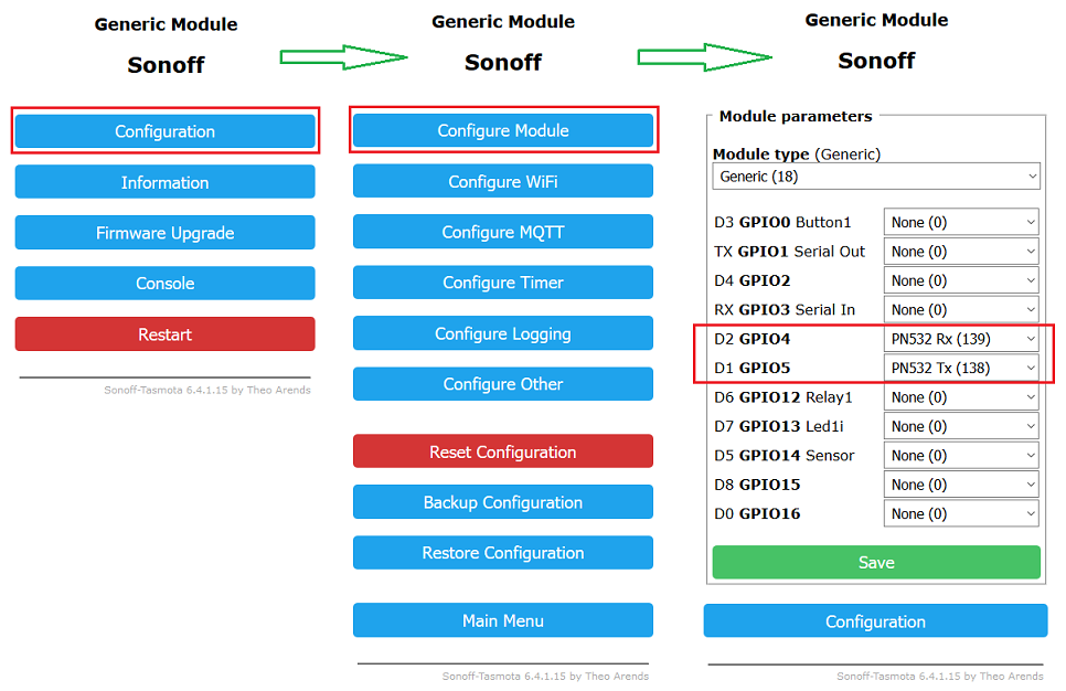
The module will reboot when you save this configuration.
Configuring and Connecting the PN532 to your ESP8266 based module
First make sure that your device is powered off and that all power connections are removed.
As mentioned earlier the PN532 breakout boards usually have pins broken out for all three protocols supported by the PN532 but we are only interested in the HSU interface as that is all the driver currently supports.
For this reason breakout boards have either micro dip switches as shown in the image below, or they have pads on the PC board which you need to bridge out with solder to select which mode the PN532 will operate in.
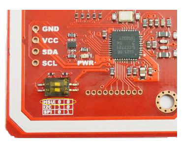
After selecting the correct protocol mode and connecting the HSU TX/RX pins of the PN532 to the pins you configured on your ESP8266 board you can power it up and the PN532 should be detected automatically.
During start-up the following information should be visible in your console output:
00:00:00 NFC: PN532 NFC Reader detected (V1.6)
If the device was not found please check your wiring and configuration and confirm that everything is as it should be.
Using the PN532 on Tasmota
Tasmota will scan for a new card detect 4 times per second and if found will report it via immediate telemetry and in addition cause an event if you chose to uncomment #define USE_PN532_CAUSE_EVENTS prior to compiling your firmware.
The output on the console will look similar to the below when a new card is detected
18:23:24 MQT: tele/tasmota/SENSOR = {"Time":"2019-01-10T18:23:24","PN532":{"UID":"94D8FC5F", "DATA":""}}
18:23:24 MQT: stat/tasmota/RESULT = {"Event":"Done"}
18:23:25 MQT: stat/tasmota/RESULT = {"Event":"Done"}
The UID of the card/tag is reported and any text stored in BLOCK 1 of a Mifare Classic card (up to 15 characters in length) is reported in the DATA field of the JSON sent via telemetry. Please note that the DATA field cannot contain spaces.
The content of the DATA on BLOCK 1 of a Mifare Classic card can be set as follows
Sensor40 S,ILOVETASMOTA
Once executed the very next card/tag that is presented to the reader will be programmed accordingly and the data will be retained on the card/tag until either changed or erased.
To erase the content of the DATA field the following command may be used
Sensor40 E
Once executed the very next card/tag that is presented to the reader will have its BLOCK 1 erased.
Text logging of the above two actions are also presented during the process for information purposes.
Using the UID and DATA of a presented card in Tasmota
When a card is presented to the PN532 under normal operating conditions up to 3 ways of using the data is possible.
The first is the immediate telemetry generated which looks as follows
18:31:39 MQT: tele/tasmota/SENSOR = {"Time":"2019-01-10T18:31:39","PN532":{"UID":"94D8FC5F", "DATA":"ILOVETASMOTA"}}
Since this is an immediate telemetry generation as opposed to the sensor data you would normally be expected to be presented when the telemetry period occurs, this telemetry data is not directly usable on the device itself. It is generated and immediately transmitted over MQTT and the purpose of this is so that immediate action may be taken by any home automation software you are using with the data obtained from the card/tag as opposed to waiting for the telemetry period to expire and be sent with normal telemetry data.
For the purpose of using card/tag data on the device itself you will need to use rules along with the events that are caused - Remember to use events you need to uncomment the #define USE_PN532_CAUSE_EVENTS directive prior to building/compiling your firmware.
Example rule for responding to a specific UID on the device when a card/tag matching a specific UID is presented
rule on EVENT#PN532_UID=94D8FC5F do power on endon
Example output/result:
18:39:20 MQT: tele/tasmota/SENSOR = {"Time":"2019-01-10T18:39:20","PN532":{"UID":"94D8FC5F", "DATA":"ILOVETASMOTA"}}
18:39:20 MQT: stat/tasmota/RESULT = {"Event":"Done"}
18:39:20 RUL: EVENT#PN532_UID=94D8FC5F performs "power on"
18:39:20 MQT: stat/tasmota/RESULT = {"POWER":"ON"}
18:39:20 MQT: stat/tasmota/POWER = ON
18:39:20 MQT: stat/tasmota/RESULT = {"Event":"Done"}
Example rule for responding to a specific DATA content that was previously programmed to one or more cards using the Sensor40 S,xxxx command
on EVENT#PN532_DATA=ILOVETASMOTA do power on endon
18:41:12 MQT: tele/tasmota/SENSOR = {"Time":"2019-01-10T18:41:12","PN532":{"UID":"94D8FC5F", "DATA":"ILOVETASMOTA"}}
18:41:13 MQT: stat/tasmota/RESULT = {"Event":"Done"}
18:41:13 MQT: stat/tasmota/RESULT = {"Event":"Done"}
18:41:13 RUL: EVENT#PN532_DATA=ILOVETASMOTA performs "power on"
18:41:13 MQT: stat/tasmota/RESULT = {"POWER":"ON"}
18:41:13 MQT: stat/tasmota/POWER = ON