The Burnett Smart Socket.
Introduction
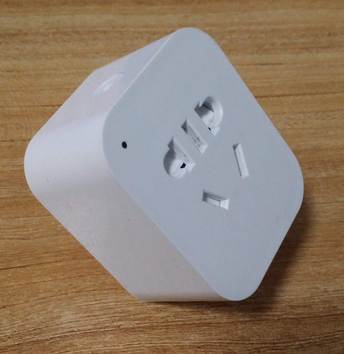
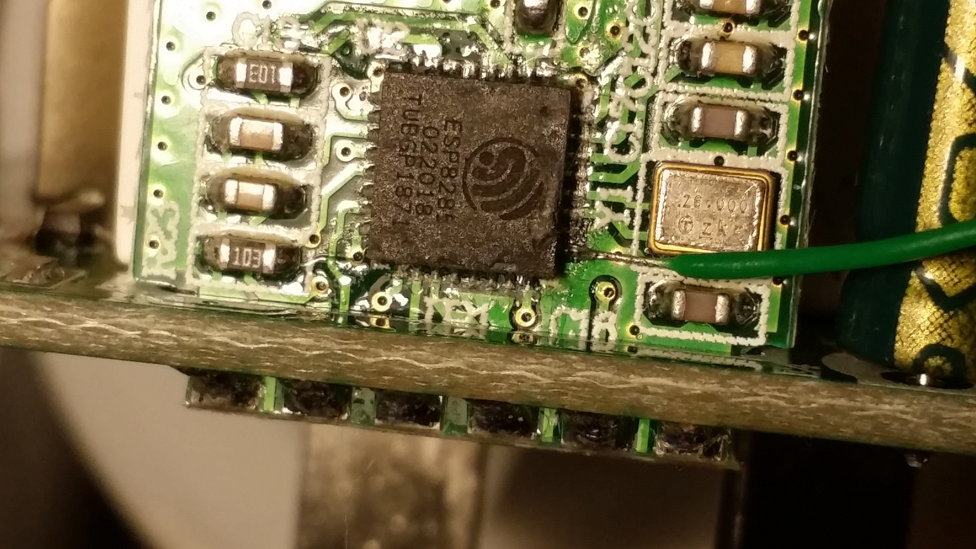
The Burnett Smart Socket BN-K01 is a smart socket that is small in size. The body is only 58mm * 48mm *34mm which can fit into smaller places. It is equipped with an ESP8285 which makes it possible to flash sonoff-tasmota. However, you need to manually wire the Tx and Rx from the chip for flashing.
This guide provides details on how to prepare the socket for the initial flashing with sonoff-tasmota code.
What is it?
As the other Sonoff's do, this smart socket uses EWeLink app to control. It’s pretty well made and there is a shutter to close off the live socket holes when a plug is removed. Besides, it is pretty cheap in Taobao (it costs no more than USD 6). 
Disassembly
*** WARNING - Opening the unit potentially exposes mains voltages that can kill. You proceed beyond here entirely at your own risk. ***
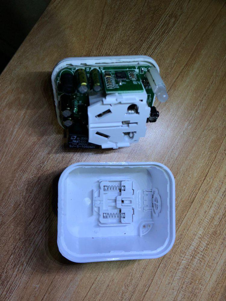
There are no screws. And unfortunately it is precisely glued, so to disassemble you need to find a thin yet strong tool to pull it open.
Inside there is a main board with most of the components on the top. The Wi-Fi and control comes from a small daughter board, soldered on the left of the main board.
Unfortunately I cannot tear down the plastic around the main board, so I don't have a clear look for the back of the daughter board.
Hookup
Unless you are just curious, there’s no real need to unsolder the main board. You can get at everything you need to re-flash it on the top side of the daughter board.
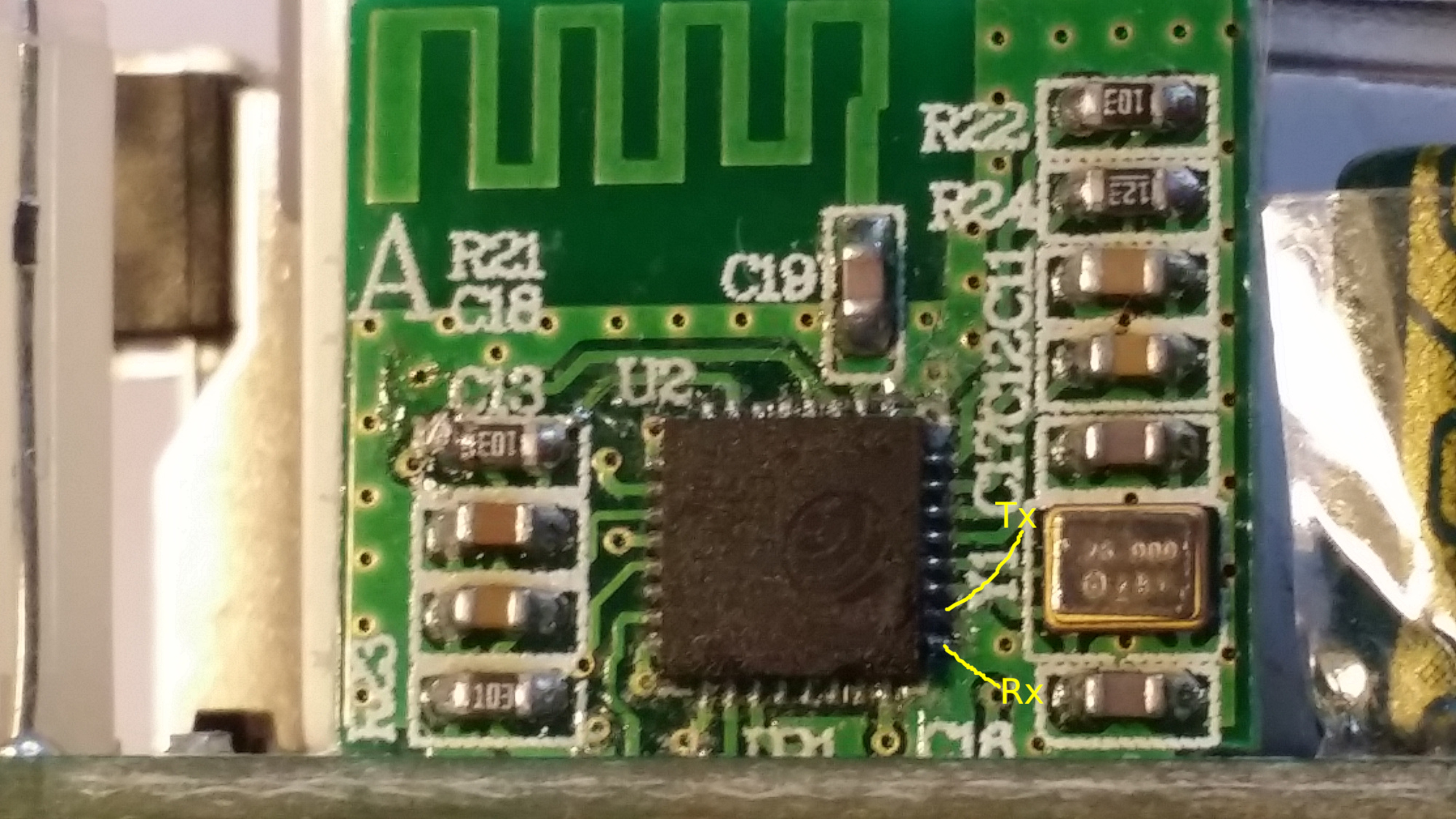
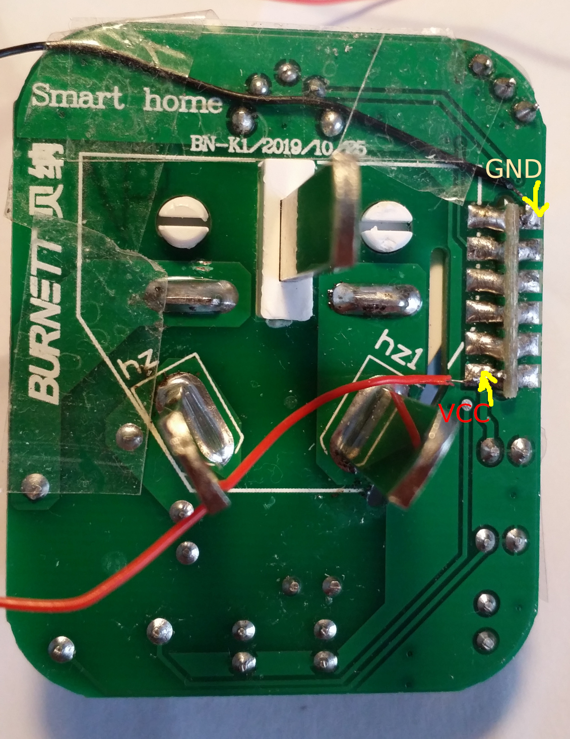
For flashing you need to solder the VCC and GND from the back. As shown in the picture, the GND is the top right pad while the VCC is the bottom left pad.
While unfortunately, the Rx and Tx is not connected, so you have to wire directly to the ESP8285. It can be very hard if you are not familiar with soldering.
The GPIO0 is connected to the button so no wiring is needed.
Building Firmware
The process for building the firmware for the Burnett BN-K01 is basically the same as for the Sonoff with a few additional changes.
- You need to set the board to "Generic ESP8285 Module"
- The crystal frequency is 26MHz.
Flash the Firmware
Hold the button when you connect the VCC and GND to make the ESP8285 boot into flash mode. After it boots, you no longer need to hold it.
Configure
After you flashed and booted the Burnett BN-K01, just set config it as Sonoff S2x, then it will work.