Yet another MagicHome RGB controller. I specifically had this one.
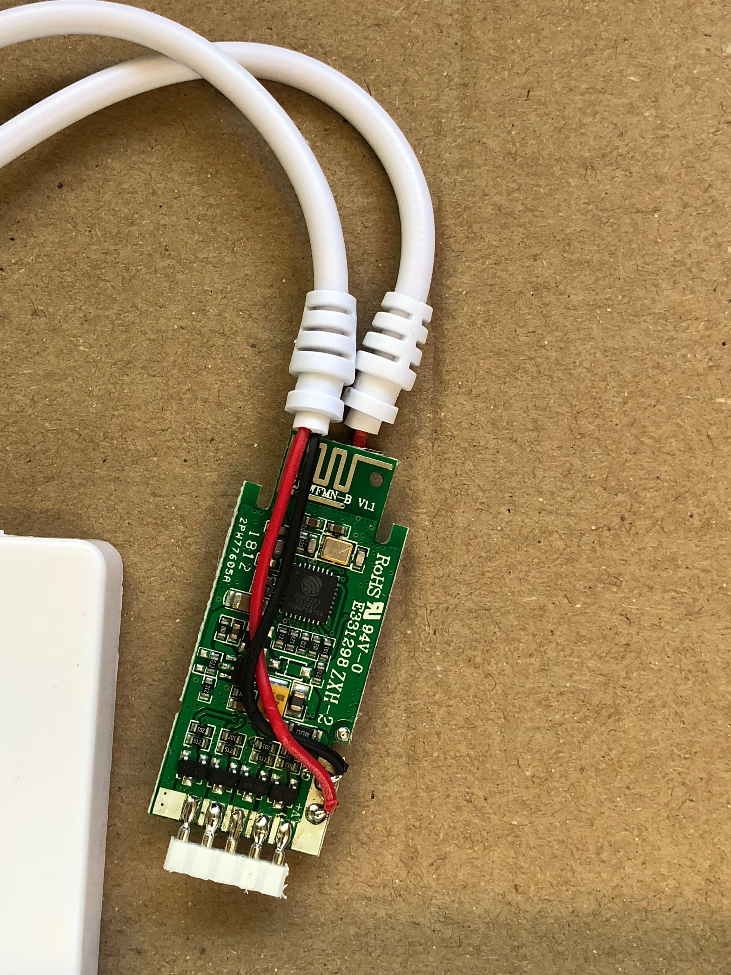
Aside from it going 9-28v, there are no other external model numbers etc, however opening it up revealed a very different configuration inside, using an ESP8285 chip directly on the board.

(Right click and view the original image to see the full size image for all images below)
Identifying this board
Looking closely you can see it's an ESP8285, on the main board, it has the part number: ZJ-WFMN-A V1.1, ZJ-WFMN-B V1.1 or ZJ-WFMN-C V1.1

Arilux devices
The devices are similar to the Arilux devices. Here is an overview:
| Model | Color Support | Voltages (sometimes) | Remote | Link |
|---|---|---|---|---|
| LC01 | RGB | 5-28V | None | Banggood |
| LC02 | RGBW | 9-12V (5-28V) | None | Banggood |
| LC03 | RGB | 5-28V | IR | Banggood |
| LC04 | RGBW | 9-12V (5-28V) | IR | Banggood |
| LC08 | RGBWW | 5-28V | None | Banggood |
| LC09 | RGB | 5-28V | RF | Banggood |
| LC10 | RGBW | 9-28V | RF | Banggood |
| LC11 | RGBWW | 9-28V | RF | Banggood |
Flashing
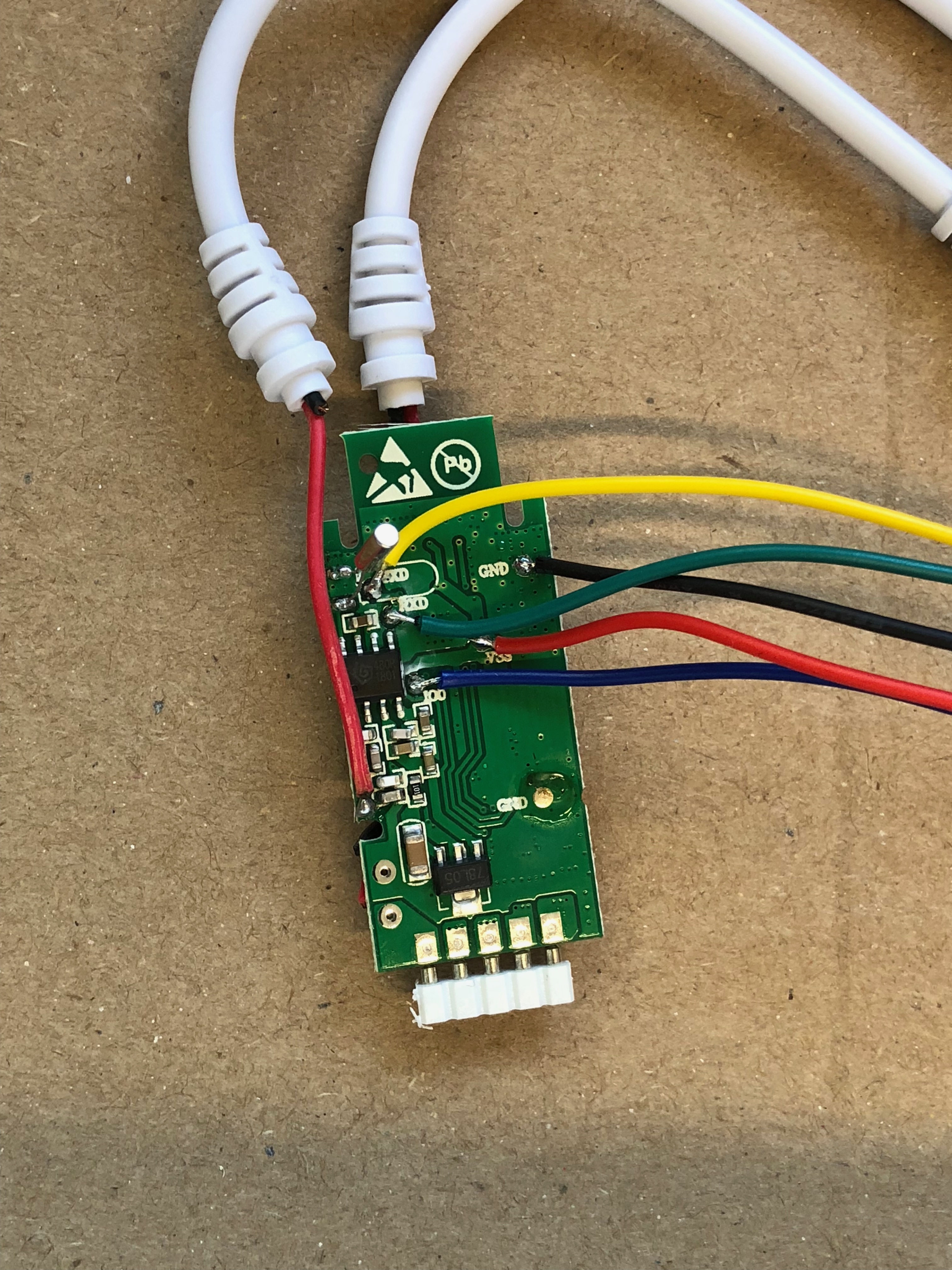
I found that on the back it has pads to solder to so you can flash it.

The IO0 port is GPIO0 that needs to be pulled to ground when powered on for flashing (as per all ESP devices). I soldered cables to each of these. Note that some are very close to other pads, so be careful. If you want to avoid soldering, also pogo pins work well with the pads.
Configuration
Once flashed, I configured it as follows (using Tasmota v6.7.1):
ZJ-WFMN-B V1.1 (RGBW-Version) alias Arilux LC02
| Field | Value |
|---|---|
| Module type | 18 Generic |
| D1 GPIO5 | 38 PWM2 |
| D6 GPIO12 | 39 PWM3 |
| D7 GPIO13 | 40 PWM4 |
| D5 GPIO14 | 37 PWM1 |
ZJ-WFMN-A V1.1 (RGBW Version with IR) alias Arilux LC04
| Field | Value | Function |
|---|---|---|
| Module type | 18 Generic | Module type |
| D2 GPIO4 | 51 IRRecv | IR Remote (optional, view console for debugging!) |
| D1 GPIO5 | 38 PWM2 | BLUE |
| D6 GPIO12 | 37 PWM1 | RED |
| D7 GPIO13 | 39 PWM3 | GREEN |
| D8 GPIO15 | 40 PWM4 | WHITE |
ZJ-WFMN-A V1.1 (RGB version) alias Arilux LC01
Automatic configuration:
| Field | Value | Function |
|---|---|---|
| Module type | 37 Arilux LC01 | Module type |
Manual configuration:
| Field | Value | Function |
|---|---|---|
| Module type | 18 Generic | Module type |
| D1 GPIO5 | 37 PWM1 | RED |
| D6 GPIO12 | 38 PWM2 | GREEN |
| D7 GPIO13 | 39 PWM3 | BLUE |
ZJ-WFMN-A V1.1 (RGB version with IR) alias Arilux LC03
| Field | Value | Function |
|---|---|---|
| Module type | 18 Generic | Module type |
| D2 GPIO4 | 51 IRRecv | IR Remote |
| D1 GPIO5 | 37 PWM1 | RED |
| D6 GPIO12 | 38 PWM2 | GREEN |
| D7 GPIO13 | 39 PWM3 | BLUE |
ZJ-WFMN-C V1.1 (monochrome version)
| Field | Value |
|---|---|
| Module type | 18 Generic |
| D6 GPIO12 | 37 PWM1 |
With all that done, one of the critical things I needed to do so I could set the colors was to run the command to set SetOption15 to 1. For me, this was sending the MQTT command (you will need to adjust for your config):
mosquitto_pub -t 'cmnd/rgbled/SetOption15' -m '1'
Once the above was done and the device rebooted, I could set the colors using commands such as (to turn on red and white full):
mosquitto_pub -h openhab.sf -t 'cmnd/rgbled/color' -m '#ff0000ff'
RF control
If you have an RF variant, you will want to configure the GPIOs like this:
  { "MagicHome RF",    // Magic Home RF (ESP8266) - (Arilux LC10)
     GPIO_USER,        // GPIO00 Optional Button
     GPIO_USER,        // GPIO01 Serial RXD and Optional sensor
     GPIO_LED1_INV,    // GPIO02 Blue onboard LED (optional)
     GPIO_USER,        // GPIO03 Serial TXD and Optional sensor0
     GPIO_ARIRFRCV,    // GPIO04 RF receiver input
     GPIO_PWM2,        // GPIO05 RGB LED Green
     0, 0, 0, 0, 0, 0, // Flash connection
     GPIO_PWM3,        // GPIO12 RGB LED Blue
     GPIO_PWM4,        // GPIO13 RGBW LED White
     GPIO_PWM1,        // GPIO14 RGB LED Red
     GPIO_LED2_INV,    // GPIO15 RF receiver control
     0, 0
  },
or like this:
  { "MagicHome RF",    // Magic Home RF (ESP8285) - (IRrecv)
     GPIO_USER,        // GPIO00 Optional Button
     GPIO_USER,        // GPIO01 Serial RXD and Optional sensor
     GPIO_LED1_INV,    // GPIO02 Blue onboard LED (not soldered)
     GPIO_USER,        // GPIO03 Serial TXD and Optional sensor0
     GPIO_IRRECV,      // GPIO04 IR receiver input
     GPIO_PWM1,        // GPIO05 RGB LED Green
     0, 0, 0, 0, 0, 0, // Flash connection
     GPIO_PWM2,        // GPIO12 RGB LED Blue
     GPIO_PWM3,        // GPIO13 RGBW LED White
     0, 0, 0
  },
After choosing the correct module type in your Tasmota configuration, press a key on the remote after boot for the device to learn your code.
Full Set of rules for IR remote
Each rule can only be 511 characters long, some of the colors below use the built in predefined shortcut color numbers.
mosquitto_pub -t 'cmnd/RGBled/rule1' -m 'On IrReceived#Data=0x00FF906F Do Dimmer + EndOn On IrReceived#Data=0x00FF9867 Do Color2 1 EndOn On IrReceived#Data=0x00FFE817 Do HSBColor1 13 EndOn On IrReceived#Data=0x00FF02FD Do HSBColor1 23 EndOn On IrReceived#Data=0x00FF50AF Do HSBColor1 33 EndOn On IrReceived#Data=0x00FF38C7 Do HSBColor1 43 EndOn On IrReceived#Data=0x00FFB847 Do Dimmer - EndOn On IrReceived#Data=0x00FFD827 Do Color2 2 EndOn On IrReceived#Data=0x00FF48B7 Do HSBColor1 140 EndOn On IrReceived#Data=0x00FF32CD Do HSBColor1 160 EndOn'

mosquitto_pub -t 'cmnd/RGBled/rule2' -m 'Rule2 On IrReceived#Data=0x00FF7887 Do HSBColor1 180 EndOn On IrReceived#Data=0x00FF28D7 Do HSBColor1 200 EndOn On IrReceived#Data=0x00FFF807 Do Power 0 EndOn On IrReceived#Data=0x00FF8877 Do Color2 3 EndOn On IrReceived#Data=0x00FF6897 Do HSBColor1 260 EndOn On IrReceived#Data=0x00FF20DF Do HSBColor1 280 EndOn On IrReceived#Data=0x00FF708F Do HSBColor1 300 EndOn On IrReceived#Data=0x00FFF00F Do HSBColor1 320 EndOn'

mosquitto_pub -t 'cmnd/RGBled/rule3' -m 'Rule3 On IrReceived#Data=0x00FFB04F Do Power 1 EndOn On IrReceived#Data=0x00FFA857 Do Color2 12 EndOn On IrReceived#Data=0x00FFB24D Do Backlog Power 0; WakeupDuration 1; Dimmer 100; Wakeup EndOn On IrReceived#Data=0x00FF00FF Do Backlog Power 0; WakeupDuration 5; Wakeup EndOn On IrReceived#Data=0x00FF58A7 Do Backlog Scheme 2; Speed 1 EndOn On IrReceived#Data=0x00FF30CF Do Backlog Scheme 3; Speed 5 EndOn'
A Google Sheets Document to edit the desired actions and create the three needed rules is linked here.
After setting the rules you need to activate them with the following:
mosquitto_pub -t 'cmnd/RGBled/rule1' -m 'ON'
mosquitto_pub -t 'cmnd/RGBled/rule2' -m 'ON'
mosquitto_pub -t 'cmnd/RGBled/rule3' -m 'ON'
The hex codes for the "Data" value come from the data tag when looking at the JSON sent via MQTT. You can also view this data on the Tasmota console screen. From here you can program it to do whatever you want using Rules.